Atomic force microscope

An atomic force microscope (AFM) measures the height of a surface by moving a cantilevered tip across a surface and measuring the motion of the cantilever as it moves across the surface. The AFM and similar instruments allow visualization of surface structure at the nanometer scale. In tapping mode the cantilever is vibrated, and the amplitude of vibration is controlled by feedback. In contact mode the cantilever is in contact with the sample, and its bending is controlled by feedback. In both cases control is actuated by a piezo element that controls the vertical position of the cantilever base (or the sample). The control system has a direct influence on picture quality and scanning rate.
AFM in contact mode
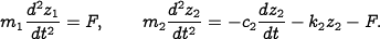
A simple model of an AFM in contact mode is obtained by assuming that the piezo crystal generates
a force  between the masses and that there is a damping
  in the
spring. Let the positions of the center of the masses be
in the
spring. Let the positions of the center of the masses be  and
and
 . A momentum balance gives the following model for the system:
Let the elongation of the piezo element  be the control
variable and the height of the cantilever base be the
output. Eliminating the variable
in equations \eqref{eq:afm:trampoline} and substituting
be the control
variable and the height of the cantilever base be the
output. Eliminating the variable
in equations \eqref{eq:afm:trampoline} and substituting  for gives the model

The piezo stack can be modeled by a second-order system with undamped natural frequency  and damping ratio
  . The dynamics are then described by the linear system
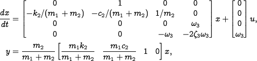
where the input signal is the drive signal to the amplifier and the output is the elongation of the piezo.
MATLAB files:
- afm_data.m - MATLAB file with the parameters of an AFM
- afm_freqresp.m - AFM frequency response (Example 5.9)
AFM in tapping mode
The dynamics of the tapping mode of an atomic force microscope are dominated by the damping of the cantilever vibrations and the system that averages the vibrations. Modeling the cantilever as a spring-mass system with low damping, we find that the amplitude of the vibrations decays as  , where
  is the
damping ratio and
is the
damping ratio and  is the undamped natural frequency of the cantilever. The cantilever dynamics can thus be modeled by the transfer function
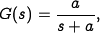
where  . The averaging process can
be modeled by the input/output relation
. The averaging process can
be modeled by the input/output relation
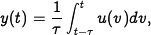
where the averaging time is a multiple  of the period of the
oscillation
of the period of the
oscillation  . The dynamics of the piezo scanner can be
neglected in the first approximation because they are typically much
faster than
. The dynamics of the piezo scanner can be
neglected in the first approximation because they are typically much
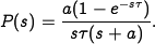
faster than  . A simple model for the complete system is thus given
by the transfer function
. A simple model for the complete system is thus given
by the transfer function
MATLAB files:
- afmtap_integral.m - Nyquist and Bodep lots for AFM in tapping mode with integral control (Example 10.2)
- afmtap_zntuning.m - Ziegler-Nichols tuning for an AFM in tapping mode (Example 10.4)
AFM nano positioner
The horizontal motion of an AFM is typically modeled as a spring-mass system with low damping. The normalized transfer function is given by
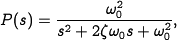
where the damping ratio typically is a very small number, e.g.,
 .
.
MATLAB files:
- afmpos_integral.m - AFM nanopositioning systems with integral control (Example 9.9)
References
- D. Sarid. Atomic Force Microscopy. Oxford University Press, Oxford, UK, 1991.
- G. Schitter. High performance feedback for fast scanning atomic force microscopes. Review of Scientific Instruments, 72(8):3320–3327, 2001.
- G. Schitter, K. J. Åström, B. DeMartini, P. J. Thurner, K. L. Turner, and P. K. Hansma. Design and modeling of a high-speed AFM-scanner. IEEE Transactions on Control System Technology, 15(5):906–915, 2007.