PID Control
| Prev: Frequency Domain Analysis | Chapter 10 - PID Control | Next: Frequency Domain Design |
This chapter describes the use of proportional integral derivative (PID) feedback for control systems design. We discuss the basic concepts behind PID control and the methods for choosing the PID gains.
Textbook Contents
|
Lecture Materials
Supplemental Information
|
Chapter Summary
This chapter describes the design and use of PID (proportional-integral-derivative) control:
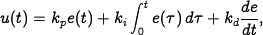
The basic PID controller has the form
where
 is the control signal and
  is the control error. The control
signal is thus a sum of three terms: a proportional term that is proportional to the error, an integral term that is proportional to the integral of the error, and a derivative term that is proportional to the derivative of the error.
is the control error. The control
signal is thus a sum of three terms: a proportional term that is proportional to the error, an integral term that is proportional to the integral of the error, and a derivative term that is proportional to the derivative of the error.
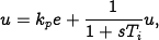
Integral action guarantees that the process output agrees with the reference in steady state and provides an alternative to including a feedforward term for tracking a constant reference input. Integral action can be implemented using automatic reset, where the output of a proportional controller is fed back to its input through a low pass filter:
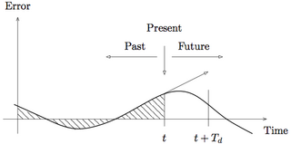
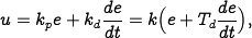
Derivative action provides a method for predictive action. The input-output relation of a controller with proportional and derivative action is
where
 is the derivative time constant. The action of a controller with proportional and derivative action can be interpreted as if the control is made proportional to the predicted process output, where the prediction is made by extrapolating the error
  time units into the future using the tangent to the error curve.
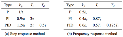
PID gains can be determined using Ziegler-Nichols tuning rules. The step response method characterizes the open loop response by the parameters
 and
and  illustrated below (left):
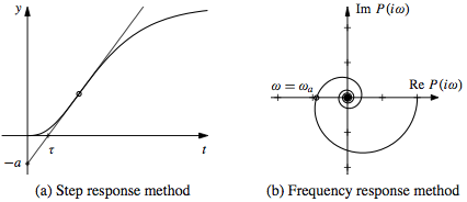
The frequency response method characterizes the process dynamics by the point where the Nyquist curve of the process transfer function first intersects the negative real axis and the frequency
 where this occurs (above, right). The corresponding PID gains are given in the following table:
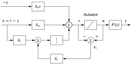
Integral windup can occur in a controller with integral action when actuator saturation is present. In this situation, the system runs open loop when the actuator is saturated and the integral error builds up, requiring the system to overshoot in order to remove the integrated error. Anti-windup compensation can be used to minimize the effects of integral windup by feeding back the difference between the commanded input and the actual input, as illustrated below:
A number of variations of PID controllers are useful in implementation. These include filtering the derivative, setpoint weighting and other variations in how the derivative and integral actions are formulated. PID controllers can be implemented using analog hardware, such as operational amplifiers, or via digital implementations on a computer.


Frequently Asked Questions
Errata
|
MATLAB codeThe following MATLAB scripts are available for producing figures that appear in this chapter.
See the software page for more information on how to run these scripts. Additional Information |